In the rapidly evolving world of electronics, the demand for high-performance multilayer Rigid-Flex PCBs is on the rise. These advanced circuit boards combine the benefits of both rigid and flexible PCBs, allowing for innovative designs that can fit into compact spaces while maintaining high reliability and performance. As a leading multilayer PCB manufacturer, Capel Technology understands the intricacies involved in the design and manufacturing of these complex boards. This article explores the optimization methods for circuit design in multilayer Rigid-Flex PCBs, ensuring that they meet the rigorous demands of modern electronic applications.
1. Reasonable Setting of Component Printed Line Spacing
One of the primary considerations in the design of multilayer Rigid-Flex PCBs is the spacing between printed lines and components. This spacing is crucial for ensuring electrical insulation and accommodating the manufacturing process. When high-voltage and low-voltage circuits coexist on the same board, it is essential to maintain a sufficient safety distance to prevent electrical interference and potential failures. Designers must carefully evaluate the voltage levels and the required insulation to determine the optimal spacing, ensuring that the board operates safely and efficiently.
2. Line Type Selection
The aesthetic and functional aspects of a PCB are significantly influenced by the selection of line types. For multilayer Rigid-Flex PCBs, the corner patterns of the wires and the overall line type must be chosen with care. Common options include 45-degree angles, 90-degree angles, and arcs. Acute angles are generally avoided due to their potential to create stress points that can lead to failures during bending or flexing. Instead, designers should favor arc transitions or 45-degree transitions, which not only enhance the manufacturability of the PCB but also contribute to its visual appeal.
3. Determination of Printed Line Width
The width of the printed lines on a multilayer Rigid-Flex PCB is another critical factor that impacts performance. The line width must be determined based on the current levels that the conductors will carry and their ability to resist interference. As a general rule, the greater the current, the wider the line should be. This is particularly important for power and ground lines, which should be as thick as possible to ensure waveform stability and minimize voltage drops. By optimizing line width, designers can enhance the overall performance and reliability of the PCB.

4. Anti-Interference and Electromagnetic Shielding
In today’s high-frequency electronic environments, interference can significantly impact the performance of a PCB. Therefore, effective anti-interference and electromagnetic shielding strategies are essential in the design of multilayer Rigid-Flex PCBs. A well-thought-out circuit layout, combined with appropriate grounding methods, can significantly reduce interference sources and improve electromagnetic compatibility. For critical signal lines, such as clock signals, it is advisable to use wider traces and implement sealed ground wires for wrapping and isolation. This approach not only protects sensitive signals but also enhances the overall integrity of the circuit.
5. Design of Rigid-Flex Transition Zone
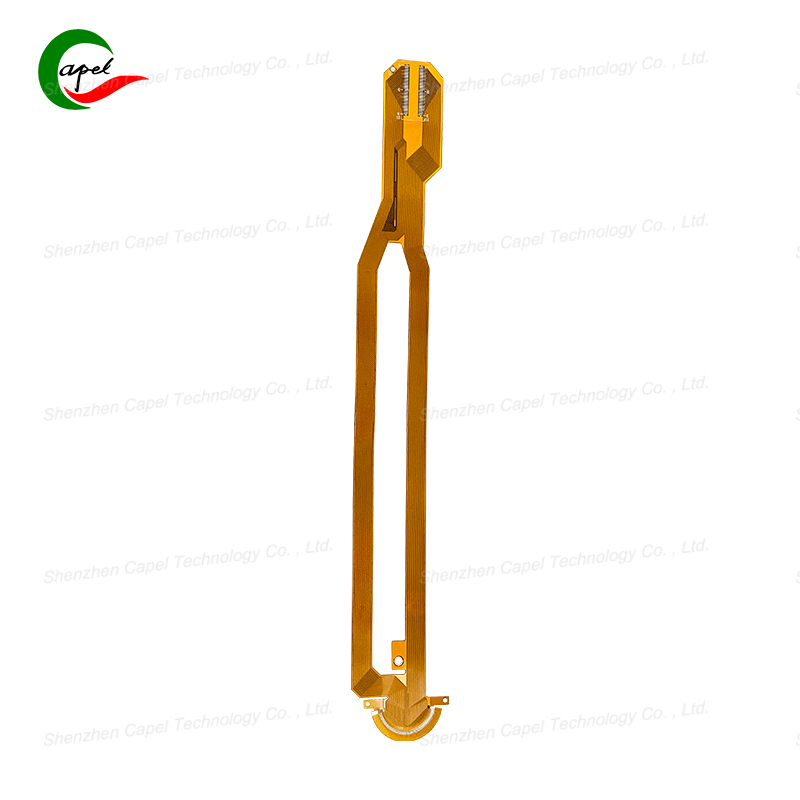
The transition zone between rigid and flexible sections of a Rigid-Flex PCB is a critical area that requires careful design. The lines in this zone should transition smoothly, with their direction perpendicular to the bending direction. This design consideration helps to minimize stress on the conductors during flexing, reducing the risk of failure. Additionally, the width of the conductors should be maximized throughout the bending zone to ensure optimal performance. It is also crucial to avoid through holes in areas that will be subjected to bending, as these can create weak points. To further enhance reliability, designers can add protective copper wires on both sides of the line, providing additional support and shielding.

Post time: Nov-12-2024
Back


